Quick Links
Counterbore Basics
- The counterbore is used to enlarge a preformed hole when a flat bottom is required or to spotface when a machine finish is required
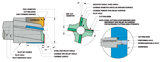
- The counterbore is an end cutting tool which may utilize a pilot to align the enlarged hole being machined with the preformed hole
- The three flute counterbore tends to reduce chatter & improves finish
Coatings are especially effective (see “Coating Selector“)
Counterbore Specifications & Tolerances
- Geometry and carbide grade appropriate for material being machined
- Carbide tips brazed to tough hardened alloy steel body, except aircraft counterbores which are not hardened
- Precision ground cutting edges
USCTI - “Taper Shank No’, refers to American Standard taper series (formerly Morse taper series) per ASME/ANSI B5.10
- Steel cutting counterbores have secondary end relief on carbide for increased cutting edge strength
- Tool diameter tolerance: plus .001″, minus .000″
- Shank diameter tolerance: plus .0000″, minus .0005″
Counterbore Problem Solving Guide
| AVOID PROBLEMS BY CAREFUL ORIGINAL SET-UP | ||
| MACHINE CONDITION | Tool holder in good condition and secure part holding fixture | |
| TOOL CONDITION | Use cutting tool recommended for material being machined. Avoid excessive tool overhang. | |
| FEEDS & SPEEDS | Start with feeds and speeds recommended for material being machined | |
| COOLANT | Coolant flow must be adequate to avoid intermittent quenching and to flush chips promptly, avoiding the recutting of hardened chips. | |
| COUNTERBORING PROBLEMS | POSSIBLE CAUSES | POSSIBLE SOLUTIONS | |
| 1. | ROUGH FINISH | Dull cutting edge | Resharpen to original tool geometry |
| Wrong feeds & speeds | Increase speed – also try reduced feed | ||
| 2. | EXCESSIVE CUTTING EDGE WEAR | Wrong feeds & speeds | Increase feed (should always be over .001″ per tooth) – especially when machining ductile or free machining materials. Also try reduced speed |
| Rough cutting edge | Lightly hone cutting edge with fine grit diamond hone | ||
| Insufficient coolant | Increase coolant flow – review type of coolant | ||
| 3. | CHIPPED CUTTING EDGE | Poor chip removal | Use tool with larger flute space – larger diameter or fewer flutes |
| Recutting work hardened chips | Increase coolant flow | ||
| Vibration | Increase rigidity of set-up, especially worn tool holders | ||
| Incorrect carbide grade | Change to tougher carbide grade | ||
| 4. | CHATTER MARKS | Insufficient machine horsepower | Use tool with fewer flutes as correct feeds & speeds must be maintained |
| Vibration | Consider climb milling Use larger diameter cutter Resharpen tool with more clearance | ||
| 5. | GLAZED FINISH | Feed too light | Increase feed |
| Dull cutting edge | Resharpen tool to original geometry | ||
| Insufficient clearance | Resharpen tool with more clearance | ||
| 6. | POOR TOOL LIFE | Excessive cratering | Increase speed or decrease feed Change to harder grade of carbide |
| Abrasive material | Decrease speed and increase feed Increase coolant flow | ||
| Hard materials | Reduce speed – rigidity very important | ||
| Insufficient chip room | Use larger diameter tool | ||
| Delayed resharpening | Prompt resharpening to original geometry will increase tool life | ||
| Thermal cracked carbide | Maintain adequate coolant flow at all times | ||
Carbide Tipped Counterbores Index and Comparison Chart
All Types For Interchangeable Pilots
| DESCRIPTION | HANNIBAL | CLEV- ELAND | ECLIPSE | GREEN- FIELD/ RTW | METCUT | MORSE | UNION | ||
| FRAC. PAGE | METRIC PAGE | TOOL TYPE | |||||||
| AIRCRAFT COUNTERBORES | |||||||||
| 3 Flutes (Similar to Craig 850 Series) | 124 | 522 | |||||||
| STRAIGHT SHANK COUNTERBORES | |||||||||
| 4 Flutes | 118 | 119 | 512 | ||||||
| 3 – 4 Flutes | 118 | 119 | 514 | 779 | SSC | 5779 | 5470 | ||
| 3 – 4 Flutes- For Steels | 122 | 123 | 510 | FAC | |||||
| TAPER SHANK COUNTERBORES | |||||||||
| 4 Flutes | 120 | 121 | 518 | ||||||
| 3 – 4 Flutes | 120 | 121 | 516 | 778 | TSC | 5780 | 5471 | ||
| 3 – 4 Flutes- For Steels | 122 | 123 | 511 | TAC | |||||
| STUB LENGTH COUNTERBORES | |||||||||
| Pin Drive- For Non-Ferrous & Cast Irons | 125 | 573 | 412 | 200 | |||||
| Pin Drive- For Steels | 125 | 574 | |||||||
| Stub Taper- For Non-Ferrous & Cast Irons | 126 | 575 | 427 | 210 | |||||
| Stub Taper- For Steels | 126 | 576 | |||||||
| Radial Drive- For Non-Ferrous & Cast Irons | 127 | 577 | 402 | 220 | |||||
| Radial Drive- For steels | 127 | 578 | |||||||
| PILOTS | |||||||||
| Short Shank | 117 | 500 | Yes | Yes | 410 | 776 | 4704 | ||

